
Intro:
The notion of randomness has consistently intrigued me, so I have always wanted to build a random number generator and play with it. Just how easy is it to generate truly random numbers as opposed to pseudo-random numbers? First of all, pseudo-random numbers are based on an algorithm so computationally they are easy to generate but also easy to copy or determine the nature of the sequence. They also ‘repeat’ their pattern eventually, even if the repeat cycle might be very large. No, no, no. I want to generate random numbers from an unpredictable natural source such as radioactive decay, cosmic rays, radio noise or ‘avalanche noise’ (hint: not the noise of snow falling down a mountain).
The Source:
In short, avalanche noise is the noisy current flow when a diode is reverse biased (voltage applied the wrong way), once that voltage is high enough to make electrons jump over the semiconductor gap the wrong way. The nifty thing is transistors have these diode junctions and so current can flow, for example, from the base to the emitter in an NPN transistor once it is reverse biased with high enough voltage. So what many circuits do to generate random noise is set up a transistor in this way, and then amplifying the current that flows, which for ‘quantum energy gap’ reasons is noisy.
An Example Circuit:
Browsing the net I came across Rob Seward’s attempts at doing this and set up his circuit since I had all the components on hand. The circuit is below:
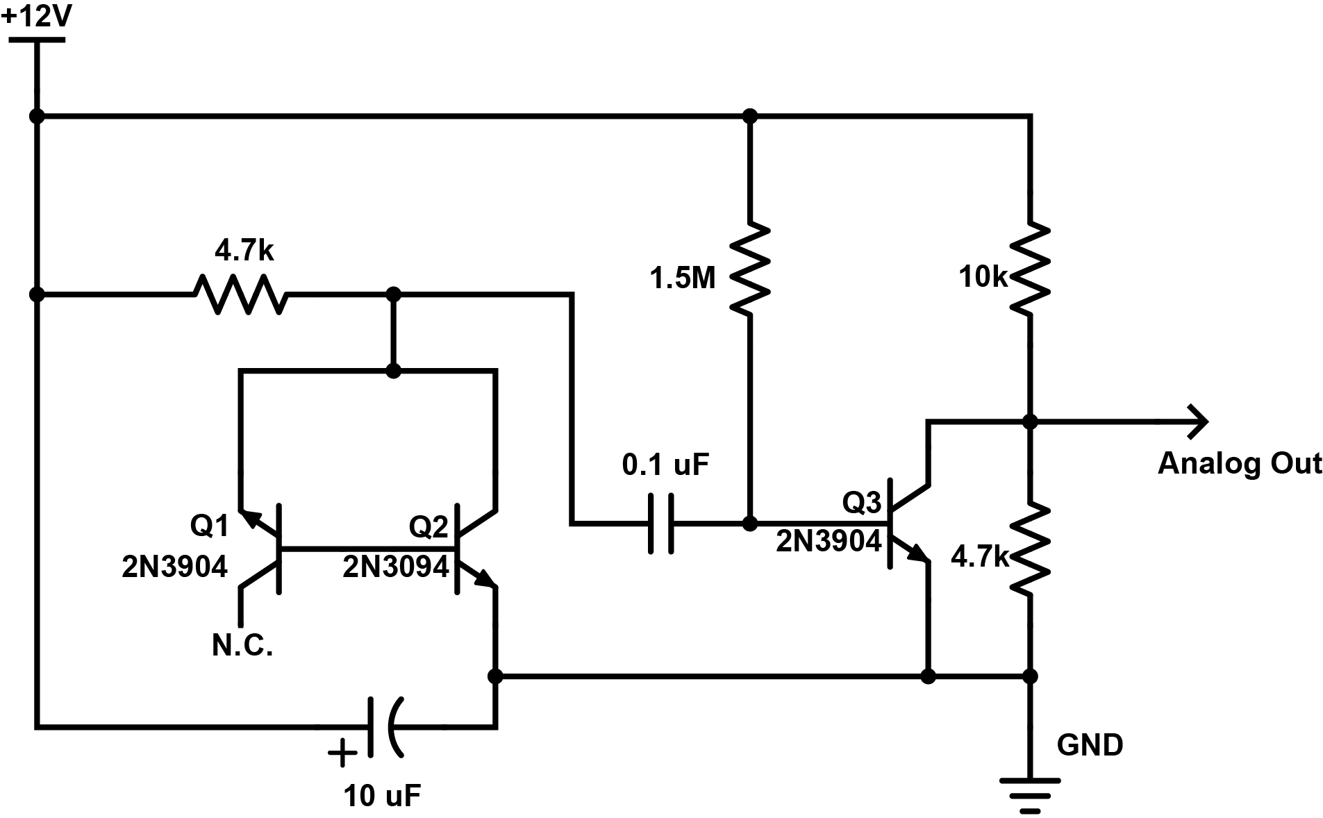
This is my understanding of this circuit: Here, Q1 is reverse biased with 12 V of EMF via the 4.7k resistor. Q2 is forward biased and so it should conduct with a small voltage drop (~0.9 V) across its base to emitter junction so the reverse bias in Q1 is actually ~11.1 volts through the 4.7k resistor. This should be enough to jump the gap as outlined in this great summary of this phenomenon by Giorgio Vazzana. If current randomly jumps the gap in Q1, this current will flow into the base of Q2 where it will be amplified by a common emitter setup and passed into the 0.1 uF capacitor. These spikes in current will pass through the capacitor and into the base of Q3, which is highly biased by the 1.5M resistor. I think whats going on here is this transistor is set up to be a switch – this high bias turns the collector to emitter current essentially off, so any current that flows into its base will turn it on. Thus a voltage appears at its collector (its also in common emitter mode). This voltage is divided by the two resistors of 10k and 4.7k and presented as an analog out signal.
I put this together and applied the analog out and a ground to some earbuds I had lying around. Faint noise!
I quickly wired up an arduino to take sample measurements of the voltage via an analogRead(). The values were peaking out at around 260 out of 1023 where 1023 would be a voltage of 5V. So Im seeing peak voltage here of about 1.25V. Ultimately I want to read these voltages with an ESP8266 unit or a raspberry pi which can only safely sample an analog voltage of 1V so I needed to play with the voltage divider. I’m not entirely sure why this works but I replaced the 10k resistor with a 22k resistor and the 4.7k resistor with a 10k resistor, which in turn dropped the analog reads to maximum reads of about 110 – or a little over half a volt. This is nice and safe.
The code I used for the arduino is here:
/*
 Read analog signal on pin A0

*/

const int analogInPin = A0; // Analog pin that noise is fed at

int sensorValue = 0; // Inital sensor value
 int low = 30; // Set a low value to be surpassed
 int high = 40; // Set a high value to be surpassed
 void setup() {
 // initialize serial communications at 9600 bps:
 Serial.begin(9600);
 }

void loop() {
 // read the analog in value:
 sensorValue = analogRead(analogInPin);

// if value is higher than ever recorded, lets note it
 if (sensorValue > high) {
 Serial.print("high: ");
 Serial.println(sensorValue);
 high = sensorValue;
 }
 // if value is lower than ever recorded, lets note it
 if (sensorValue < low) {
 Serial.print("low: ");
 Serial.println(sensorValue);
 low = sensorValue;
 }

// wait 2 milliseconds before the next read
 // thats 500 samples per second
 delay(2);
 }
Whats next:
The next step before making an extensive set of analog reads is to add an OP amp so I can drive a speaker and listen to the noise out loud and make some recordings for here. Until then…
A quick heads up (I have a cold and sound awful):


Pingback: Random Number Generation Part II – Some Data Analysis | Scott Robson Blog
Pingback: Random Number Generation Part II – Some Data Analysis – Scott Anthony Robson
Fascinating to see the hardware behind true randomness! If you’re ever looking for a quick way to generate cryptographically secure random numbers in custom ranges for testing or statistical sampling, check out the Random Number Generator tool on ToolGrid. It runs in your browser, lets you specify min and max values, supports bulk generation, and exports results: https://www.toolgrid.io/clusters/dev-utilities/generators/random-number-generator-v1